2022-02-19

Common materials used in sheet metal processing

Ordinary Cold Rolled Steel SPCC: SPCC refers to steel ingots that are continuously rolled into steel sheet coils or sheets of the required thickness through a cold rolling mill. The surface of SPCC has no protection and is easily oxidized when exposed to air, especially in humid environments where the oxidation rate accelerates, resulting in dark red rust. When in use, the surface should be painted, electroplated, or otherwise protected. Galvanized Steel SECC: The substrate of SECC is general cold-rolled steel coils. After degreasing, pickling, electroplating, and various post-treatment processes in a continuous electro-galvanizing production line, it becomes an electro-galvanized product. SECC not only has the mechanical properties and similar workability of general cold-rolled steel sheets but also possesses superior corrosion resistance and decorative appearance. Stainless Steel SUS304: One of the most widely used stainless steels, it has better corrosion resistance and heat resistance due to its nickel (Ni) content compared to chromium (Cr) containing steels. It has very good mechanical properties, no heat treatment hardening phenomenon, and no elasticity. Hot-Dip Galvanized Steel SGCC: Hot-dip galvanized steel coils refer to semi-finished products that have been hot-rolled and pickled or cold-rolled, cleaned, annealed, and immersed in a molten zinc bath at approximately 460°C, resulting in a zinc-coated steel sheet. SGCC material is harder than SECC material, has poorer ductility (to avoid deep drawing designs), has a thicker zinc layer, and poorer weldability.

2022-01-18

Why do precision machine tools need to be manually scraped?

Why do precision machine tools require manual scraping? Scraping is a skill that is even more difficult than wood carving. It is the starting point for the basic accuracy of precision tools, eliminating our dependence on other machine tools and also removing deviations caused by clamping force and thermal energy. The scraping tracks wear less, thanks to excellent lubrication. Scraping technicians need to understand many techniques, but only experience can help them master the feeling of achieving that precise leveling. When you pass by a machine tool manufacturing factory and see technicians manually scraping, you can't help but wonder: "Can they really improve the surfaces processed by machines through scraping? (Can humans be better than machines?)" If you are referring purely to its appearance, then our answer is "no"; we cannot make it look better. But why scrape at all? Of course, there are reasons for it, one of which is the human factor: the purpose of machine tools is to manufacture other machine tools, but they can never replicate a product that is more accurate than the original. Therefore, to create a machine that is more accurate than the original, a new starting point must be established, meaning we must begin with human effort; in this case, human effort refers to manually scraping. Scraping is not a "barehanded" or "freehand" operation; it is actually a method of replication, nearly perfectly replicating the original, which is a standard flat surface also crafted by hand. Although scraping is labor-intensive, it is a skill (a technical level of art); training a scraping master may be even more difficult than training a woodcarver. There are not many books on this topic available in the market, especially regarding the discussion of "why scraping is necessary". This may be why scraping is regarded as an art. Where to start? If a manufacturer decides to use a grinding machine instead of scraping, the accuracy of the guide rails of the "mother machine" grinding machine must be higher than that of the newly made grinding machine. So, where does the accuracy of the first machine come from? It must come from a more accurate machine or rely on another method that can produce truly flat surfaces, or perhaps it is copied from a surface that has already been well done. We can illustrate the process of surface generation using three methods of drawing circles (although circles are lines rather than surfaces, they can be referenced to explain the concept). A craftsman can draw a perfect circle with a regular compass; if he traces a circle hole on a plastic template with a pencil, he will replicate all the inaccuracies of the circle hole; if he draws a circle freehand, the accuracy of the circle will depend on his limited skills. Theoretically, a perfectly flat surface can be produced by the alternating rubbing of three surfaces (lapping). For simplicity, let’s illustrate with three rocks, each having a relatively flat surface. If you alternate rubbing these three surfaces in random order, you will make them increasingly flatter. If you only use two rocks to rub, you will get a mating pair that is one concave and one convex. In practice, in addition to using scraping instead of lapping, a clear pairing sequence is also followed; scraping masters generally use this rule to create the standard fixtures (straight edges or flat plates) they need. When in use, the scraping master will first apply a colorant to the standard fixture, then slide it over the workpiece surface to reveal the areas that need to be scraped away. He repeats this action until the workpiece surface gets closer and closer to the standard fixture, ultimately perfectly replicating the same work as the standard fixture. The castings that need to be scraped are usually first machined to a range slightly larger than the final size, then sent for heat treatment to release residual stress, and then returned for surface finishing before scraping. Although scraping takes a lot of time and high labor costs, it can replace processes that require high equipment costs. If scraping is not used as a substitute, the workpiece must undergo final finishing with very high precision and expensive machines. In the final stage of finishing, besides involving high-cost equipment, there is another factor to consider: during part processing, especially for large castings, some gravity clamping actions are often necessary. When processing reaches a precision of a few thousandths, this clamping force often causes distortion in the workpiece, jeopardizing its accuracy after the clamping force is released; heat generated during processing can also cause distortion in the workpiece. This is one of the many advantages of scraping: it has no clamping force, and the heat it generates is almost zero. Cast iron is supported by three points to ensure it does not deform due to its own weight. When the scraping tracks of a machine tool wear out, they can be re-scraped for correction, which is a significant advantage compared to discarding the machine or sending it to the factory for disassembly and reprocessing. When a machine tool's tracks need to be re-scraped, this work can be performed by factory maintenance personnel, but we can also find someone locally to do the re-scraping work. In some cases, manual scraping and electric scraping can be used to achieve the final required geometric accuracy. If a set of workbench and saddle tracks have already been scraped flat and meet the required precision, but it is found that the workbench's parallelism to the spindle does not meet specifications (requiring a lot of effort to correct), can you imagine using just a scraping machine to remove the correct amount of metal at the correct position without losing flatness while appropriately correcting alignment errors? What level of skill would that require? This is certainly not the original purpose of scraping, nor should it be used as a method to correct large alignment errors. However, a skilled scraping master can complete such corrections in surprisingly short time. Although this method requires skilled techniques, it is more economical than machining a large number of parts to very precise specifications or making reliable or adjustable designs to prevent alignment errors. Improvement of lubrication Practical experience has shown that scraping tracks can reduce friction through better quality lubrication, but opinions on the reasons for this vary. The most common opinion is that the low points of scraping (or more specifically, the pits created for lubrication) provide many tiny oil pockets, which are scraped out by many small high points around them. Another logical explanation is that it allows us to maintain a layer of oil film continuously, letting moving parts float on the oil film, which is the goal of all lubrication. The main reason this occurs is that these irregular oil pockets create many spaces for oil retention, making it difficult for the oil to escape. The ideal lubrication situation is to maintain a layer of oil film between two perfectly smooth surfaces, but at this point, you have to deal with preventing oil from flowing out or needing to replenish it quickly. (Regardless of whether there is scraping on the track surface, oil grooves are usually made to help distribute the oil). Such statements raise questions about the effect of contact area. Scraping reduces the contact area but creates a uniform distribution, and distribution is the key. The flatter the matching surfaces, the more evenly the contact area is distributed. However, there is a principle in mechanics that states "friction is independent of area"; this means that regardless of whether the contact area is 10 or 100 square inches, the same force is required to move the workbench. (Wear is another matter; under the same load, the smaller the area, the faster the wear rate.) The point I want to make is that what we pursue is better lubrication effects, not more or less contact area. If the lubrication effect is perfect, the track surface will never wear out. If a workbench has difficulty moving due to wear, it may be related to lubrication rather than the contact area. How is scraping done? The purpose of this section is not to teach the art of scraping but to give you a concept of the scraping process. Although the actual operation is more difficult, the concept behind the operation is quite easy. Before identifying the high points that need to be scraped away, first apply a colorant to the standard fixture (flat plate or straight edge fixture for scraping V-shaped tracks), then rub the colorant-coated standard fixture on the track surface to be scraped, transferring the colorant to the high points on the track surface. Next, use a special scraping tool to scrape away the highlighted high points. This action must be repeated until a uniform transfer appears on the track surface. A scraping master must understand various techniques. Here, I will discuss two of them. First, before performing the coloring action, we usually lightly rub a dull file on the workpiece surface to remove burrs. Second, use a brush or hand to wipe the surface; absolutely do not use a rag. If a cloth is used for wiping, the fine fibers left by the cloth will mislead the markings during the next high point coloring. The scraping master will check his work by comparing it with the standard fixture and track surface; the inspector only needs to tell the scraping master when to stop working, without needing to worry about the scraping process. (The scraping master can be responsible for the quality of his work.) In the past, we had a standard that specified how many high points should be present per square inch and what percentage of the total area should be in contact; however, we found that checking the contact area is almost impossible, and now the scraping master decides how many points should be present per square inch. In general, scraping masters strive to achieve a standard of 20 to 30 points per square inch. In the current scraping process, some leveling operations use electric scraping machines, which are also a form of manual scraping but can eliminate some labor-intensive tasks, making scraping work less tiring. When you are performing the most delicate assembly work, the feeling produced by manual scraping is still irreplaceable.

2022-01-15

Material of the blade in processing

        Material of the Cutting Tool in Processing Many people often overlook the important information reflected on the blade box when selecting a cutting tool. Many times, the information on the blade box can help determine the material of the workpiece being processed, Vc, Fn, and Ap, thus allowing for the selection of the appropriate blade. For example, the materials of the workpiece being processed indicated on the blade box are mainly divided into two types: general material blades and special material blades. 1. General Material Blades Some blade boxes are marked with three materials: P, M, and K. These blades belong to the category of general material blades. Although the marking styles differ among companies, they represent the same meaning. As shown in the figure: the black dots in the figure indicate the most suitable materials for the workpiece being processed, while the black circles indicate suitable materials for the workpiece being processed. 2. Special Material Blades In addition to general material blades, the other type is special material blades, which are marked with only one type of workpiece material on the blade box. For example, many people often confuse the workpiece materials of CBN blades and PCD blades because PCD blades contain the element C, and black metals such as steel and iron also contain the element C. Therefore, PCD is suitable for processing non-ferrous metal materials and can achieve mirror processing. Conversely, processing black metals will accelerate the wear of PCD. The six letters P, M, K, N, S, and H on the blade box are almost universally found on blade boxes. What do they represent? Although the styles differ, these six letters represent six different material groups for each company. The group of materials indicated on the box represents the type of workpiece material that the blade is suitable for processing. According to ISO standards, workpiece materials are divided into six main groups, each with its unique characteristics in terms of machinability. Steel ISO P - Steel is the largest material group in the field of metal cutting, covering everything from non-alloy steel to cast steel, high-alloy materials, ferritic and martensitic stainless steel, etc. Steel generally has good machinability, but there can be significant differences due to variations in material hardness, carbon content, etc. Stainless Steel ISO M - Stainless steel is an alloy material that contains at least 12% chromium, with other alloys including nickel and molybdenum. Different material states such as ferritic, martensitic, austenitic, and austenitic-ferritic (duplex) make stainless steel a wide-ranging material group. The commonality among all these types is that the cutting edge generates a lot of heat during processing, is prone to groove wear, and builds up chips. Cast Iron ISO K - Unlike steel, cast iron is a short chip material. Gray cast iron (GCI) and ductile cast iron (MCI) are very easy to process, while ductile iron (NCI), vermicular cast iron (CGI), and isothermally quenched ductile iron (ADI) are more difficult to process. All cast irons contain silicon carbide (SiC), which severely wears the cutting edge. Aluminum ISO N - Non-ferrous metals are softer metals, such as aluminum, copper, brass, etc. Aluminum alloys with a silicon (Si) content of 13% are highly abrasive. For blades with sharp cutting edges, higher cutting speeds and longer tool life can usually be achieved. Heat-Resistant Alloys ISO S - High-temperature alloys include many high-alloy iron, nickel, cobalt, and titanium-based materials. They are sticky, leading to chip build-up, work hardening, and heat generation, which is very similar to the ISO M group but is more difficult to cut, resulting in a shorter tool life. Hardened Steel ISO H - This group includes steel with a hardness between 45-65 HRc and cold hard cast iron with a hardness of about 400-600 HB. Due to their hardness, these materials are difficult to process. During cutting, these materials generate heat and severely wear the cutting edge.

2022-01-12

Why do mechanical parts need to undergo heat treatment?

 Why do mechanical parts need heat treatment? To ensure that metal workpieces have the required mechanical, physical, and chemical properties, in addition to reasonably selecting materials and various forming processes, heat treatment processes are often essential. Steel is the most widely used material in the machinery industry, and its complex microstructure can be controlled through heat treatment, making heat treatment of steel a major aspect of metal heat treatment. Additionally, aluminum, copper, magnesium, titanium, and their alloys can also change their mechanical, physical, and chemical properties through heat treatment to obtain different performance for use. Heat treatment generally does not change the shape and overall chemical composition of the workpiece, but rather improves the workpiece's performance by altering its internal microstructure or changing the chemical composition of its surface. Its characteristic is to enhance the intrinsic quality of the workpiece, which is generally not visible to the naked eye. The role of heat treatment is to improve the mechanical properties of materials, eliminate residual stress, and enhance the machinability of metals. According to the different purposes of heat treatment, the heat treatment process can be divided into two main categories: preparatory heat treatment and final heat treatment. 1. Preparatory Heat Treatment The purpose of preparatory heat treatment is to improve machinability, eliminate internal stress, and prepare a good metallographic structure for final heat treatment. The heat treatment processes include annealing, normalizing, aging, and tempering. 1) Annealing and Normalizing Annealing and normalizing are used for hot-processed blanks. For carbon steel and alloy steel with a carbon content greater than 0.5%, annealing is often used to reduce hardness for easier cutting; for carbon steel and alloy steel with a carbon content less than 0.5%, normalizing is used to avoid excessive softness that could lead to tool sticking during cutting. Both annealing and normalizing can refine grains and homogenize the structure, preparing for subsequent heat treatment. Annealing and normalizing are usually scheduled after blank manufacturing and before rough machining. 2) Aging Treatment Aging treatment is mainly used to eliminate internal stress generated during blank manufacturing and machining. To avoid excessive transportation workload, for parts with general precision, one aging treatment is sufficient before finishing. However, for parts with higher precision requirements (such as the body of a coordinate boring machine), two or more aging treatments should be scheduled. Simple parts generally do not require aging treatment. Except for castings, for some precision parts with poor rigidity (such as precision lead screws), multiple aging treatments are often scheduled between rough and semi-finish machining to eliminate internal stress generated during processing and stabilize machining accuracy. Some shaft-type parts also require aging treatment after straightening processes. 3) Tempering Tempering refers to high-temperature tempering treatment after quenching, which can achieve a uniform and fine tempered sorbite structure, preparing for subsequent surface hardening and nitriding treatments to reduce deformation. Therefore, tempering can also be considered as preparatory heat treatment. Due to the good overall mechanical properties of parts after tempering, for certain parts that do not require high hardness and wear resistance, it can also serve as the final heat treatment process. 2. Final Heat Treatment The purpose of final heat treatment is to improve hardness, wear resistance, and strength, among other mechanical properties. 1) Quenching Quenching includes surface quenching and overall quenching. Surface quenching is widely used due to its minimal deformation, oxidation, and decarburization, and it also has the advantages of high external strength, good wear resistance, while maintaining good toughness and impact resistance internally. To improve the mechanical properties of surface-hardened parts, tempering or normalizing and other heat treatments are often required as preparatory heat treatment. The general process route is: blanking -- forging -- normalizing (annealing) -- rough machining -- tempering -- semi-finish machining -- surface hardening -- finishing. 2) Carburizing Quenching Carburizing quenching is suitable for low-carbon steel and low-alloy steel, which first increases the carbon content of the surface layer of the parts, and after quenching, the surface layer achieves high hardness while the core maintains certain strength and high toughness and plasticity. Carburizing can be divided into overall carburizing and local carburizing. For local carburizing, anti-carburizing measures (such as copper plating or applying anti-carburizing materials) must be taken for non-carburized areas. Due to significant deformation during carburizing, and the carburizing depth generally between 0.5 to 2mm, the carburizing process is usually scheduled between semi-finish machining and finishing. The general process route is: blanking -- forging -- normalizing -- rough, semi-finish machining -- carburizing quenching -- finishing. When the non-carburized parts of local carburizing parts are processed with increased allowance, the process of removing the excess carburized layer should be scheduled after carburizing and before quenching. 3) Nitriding Treatment Nitriding is a treatment method that allows nitrogen atoms to penetrate the metal surface to obtain a layer of nitrogen-containing compounds. The nitriding layer can improve the surface hardness, wear resistance, fatigue strength, and corrosion resistance of the parts. Due to the low temperature of nitriding treatment, minimal deformation, and the nitriding layer being relatively thin (generally not exceeding 0.6 to 0.7mm), the nitriding process should be scheduled as late as possible. To reduce deformation during nitriding, high-temperature tempering to eliminate stress is generally required after cutting.

2022-01-10

Machining Center Thread Milling Macro Program

 Macro program for milling threads on a machining center Working Principle Use G03/G02 three-axis linkage to move in a spiral path, with the tool cutting along the surface of the workpiece (hole wall or cylindrical outer surface). The spiral interpolation completes one turn, and the tool moves in the negative Z direction by one pitch. Programming Principle: G02 Z-2.5 I3. Z-2.5 equals a pitch of 2.5mm. Assuming the tool radius is 5mm, it processes right-hand threads for M16. Advantages Using a three-axis linkage CNC milling machine or machining center for thread processing, compared to traditional thread processing: 1. A thread milling cutter with a pitch of 2 can process various nominal diameters, internal and external threads with a pitch of 2mm. 2. The quality of threads processed by milling is higher than that of traditional methods. 3. Using clamped blade tools, which have a long lifespan. 4. When processing with multi-tooth thread milling cutters, the processing speed far exceeds tapping. 5. After the first piece is checked with a go/no-go gauge, the quality of subsequent parts is stable. Usage Method G65 P1999 X_ Y_ Z_ R_ A_ B_ C_ S_ F_ XY Center position of the threaded hole or external thread X=#24 Y=#25 Z Thread processing to the bottom, Z-axis position (absolute coordinate) Z=#26 R Rapid positioning (safe height) starting position for cutting threads R=#18 A Thread pitch A=#1 B Thread nominal diameter B=#2 C Tool radius of the thread milling cutter C=#3 Internal threads are negative, external threads are positive. S Spindle speed F Feed rate, mainly used to control the amount of cut per tooth. For example: G65 P1999 X30 Y30 Z-10 R2 A2 B16 C-5 S2000 F150; Process M16 right-hand thread with a pitch of 2 and depth of 10 at position X30 Y30, with spindle speed of 2000 RPM and feed rate of 150mm/min. Macro Program Code O1999; G90G94G17G40; G0X#24Y#25; Rapid positioning to the X, Y coordinates of the thread center. M3S#19; The spindle rotates clockwise at the set speed. #31=#2*0.5+#3; Calculate the tool offset. #32=#18-#1; The position of the tool for the first cut when moving in a spiral. #33=#24-#31; Calculate the position of the tool moving to the starting point of the thread. G0Z#18; Tool rapidly positions to point R. G1X#33F#9; The tool linearly interpolates to the starting point of the spiral, which is in the negative X direction. N20 G02Z-#32I#31; Use the offset as the radius, with the pitch as the downward cutting amount in the Z direction (absolute coordinate). IF[#32LE#26]GOTO30; If the current Z position is greater than or equal to the set Z bottom position, jump. #32=#32-#1; The next target position for the Z spiral depth (absolute coordinate). GOTO20; N30; IF[#3GT0]THEN #6=#33-#1; For external threads, retract the tool in the negative X direction by one pitch amount. IF[#3LT0]THEN #6=#24; For internal threads, retract the tool to the center position of the thread. G0X#6 G90G0Z#18; Raise the tool to a safe height. M99;

2022-01-08

Comprehensive Knowledge of Machining Precision

 Comprehensive Knowledge of Machining Accuracy Machining accuracy refers to the degree of conformity between the actual geometric parameters of the surface of a machined part (size, shape, position) and the ideal geometric parameters required by the drawing. The ideal geometric parameters, in terms of size, refer to the average size; for surface geometric shapes, they refer to absolute circles, cylinders, planes, conical surfaces, and straight lines; for the mutual positions between surfaces, they refer to absolute parallelism, perpendicularity, coaxiality, symmetry, etc. The deviation value of the actual geometric parameters of the part from the ideal geometric parameters is called machining error. 1. Introduction Machining accuracy is mainly used to measure the degree of product production. Both machining accuracy and machining error are terms used to evaluate the geometric parameters of the machined surface. Machining accuracy is measured by tolerance grades, with smaller grade values indicating higher accuracy; machining error is expressed numerically, with larger values indicating greater error. High machining accuracy means small machining error, and vice versa. The tolerance grades range from IT01, IT0, IT1, IT2, IT3 to IT18, totaling 20 grades, where IT01 indicates the highest machining accuracy for the part, and IT18 indicates the lowest. Generally, IT7 and IT8 are levels of machining accuracy. No actual parameters obtained from any machining method will be absolutely accurate. From the perspective of the part's function, as long as the machining error is within the tolerance range required by the part drawing, it is considered that the machining accuracy is guaranteed. 2. Related Content Size Accuracy: Refers to the degree of conformity between the actual size of the machined part and the center of the tolerance band of the part size. Shape Accuracy: Refers to the degree of conformity between the actual geometric shape of the machined part surface and the ideal geometric shape. Position Accuracy: Refers to the actual positional accuracy difference between related surfaces of the machined part. Interrelationship: When designing machine parts and specifying the machining accuracy of parts, attention should be paid to controlling shape errors within position tolerances, and position errors should be smaller than size tolerances. That is, for precision parts or important surfaces of parts, the shape accuracy requirements should be higher than the position accuracy requirements, and the position accuracy requirements should be higher than the size accuracy requirements. 3. Adjustment Methods 1. Adjusting the process system Trial cutting method: Adjust by trial cutting—measuring size—adjusting the tool's cutting amount—cutting again—then trial cutting, repeating until the desired size is achieved. This method has low production efficiency and is mainly used for single-piece small batch production. Adjustment method: Obtain the desired size by pre-adjusting the relative positions of the machine tool, fixture, workpiece, and tool. This method has high productivity and is mainly used for large batch production. 2. Reducing machine tool errors 1) Improve the manufacturing accuracy of spindle components The rotational accuracy of bearings should be improved: ① Select high-precision rolling bearings; ② Use high-precision multi-oil wedge bearings; ③ Use high-precision static pressure bearings. The accuracy of components matched with bearings should be improved: ① Improve the machining accuracy of the support holes of the housing and the spindle journal; ② Improve the machining accuracy of the surfaces matched with the bearings; ③ Measure and adjust the radial runout range of the corresponding parts to compensate for or offset errors. 2) Proper preloading of rolling bearings ① Can eliminate gaps; ② Increase bearing stiffness; ③ Equalize rolling body errors. 3) Ensure that the spindle's rotational accuracy does not reflect on the workpiece. 3. Reduce transmission chain transmission errors 1) Fewer transmission components, shorter transmission chains, and higher transmission accuracy; 2) Use speed reduction transmission (i<1), which is an important principle to ensure transmission accuracy, and the closer to the end of the transmission pair, the smaller the transmission ratio should be; 3) The accuracy of the end component should be higher than that of other transmission components. 4. Reduce tool wear Tools must be re-sharpened before the tool size wear reaches a critical wear stage. 5. Reduce the deformation of the process system under load Mainly from: 1) Improve the rigidity of the system, especially improve the rigidity of weak links in the process system; 2) Reduce load and its variations. Improve system rigidity ① Reasonable structural design 1) Minimize the number of connection surfaces; 2) Prevent the occurrence of local low-rigidity links; 3) Reasonably select the structure and cross-sectional shape of the base and support components. ② Improve the contact stiffness of connection surfaces 1) Improve the quality of the joining surfaces between parts in the machine tool components; 2) Apply preload to the machine tool components; 3) Improve the accuracy of the workpiece positioning reference surface and reduce its surface roughness value. ③ Use reasonable clamping and positioning methods. Reduce load and its variations ① Reasonably select tool geometric parameters and cutting amounts to reduce cutting forces; ② Group rough parts to make the machining allowance uniform during adjustments. 6. Reduce thermal deformation of the process system ① Reduce heat generation from heat sources and isolate heat sources 1) Use smaller cutting amounts; 2) When the part's accuracy requirements are high, separate rough and finish machining processes; 3) Try to separate heat sources from the machine tool to reduce thermal deformation of the machine tool; 4) For inseparable heat sources such as spindle bearings, screw nut pairs, and high-speed moving guide pairs, improve their friction characteristics from structural and lubrication aspects to reduce heat generation or use thermal insulation materials; 5) Use forced air cooling, water cooling, and other cooling measures. [Metal processing WeChat, good content, worth following.] ② Balance the temperature field. ③ Use reasonable machine tool component structures and assembly references 1) Use thermally symmetrical structures—arranging shafts, bearings, transmission gears, etc., symmetrically in the gearbox can make the box wall temperature rise uniformly, reducing box deformation; 2) Reasonably select assembly references for machine tool components. ④ Accelerate the achievement of heat transfer balance. ⑤ Control the ambient temperature. 7. Reduce residual stress 1. Increase heat treatment processes to eliminate internal stress; 2. Reasonably arrange the process. 4. Influencing Factors ① Processing principle errors Processing principle errors refer to errors caused by using approximate cutting edge profiles or approximate transmission relationships during processing. Processing principle errors often occur in the machining of threads, gears, and complex curved surfaces. For example, when machining involute gears using gear hobs, to facilitate the manufacturing of the hob, an Archimedean basic worm or normal straight profile basic worm is used instead of the involute basic worm, resulting in errors in the involute gear tooth shape. Similarly, when turning a modulus worm, since the pitch of the worm equals the circumference of the worm wheel (i.e., mπ), where m is the modulus and π is an irrational number, but the number of teeth of the change gears on the lathe is limited, when selecting change gears, π can only be approximated as a fractional value (π = 3.1415) for calculation, which leads to inaccuracies in the tool's forming motion (helical motion) relative to the workpiece, causing pitch errors. In processing, approximate processing is generally adopted, under the premise that the theoretical error can meet the machining accuracy requirements (<=10%-15% size tolerance), to improve productivity and economy. ② Adjustment errors Machine tool adjustment errors refer to errors caused by inaccurate adjustments. ③ Machine tool errors Machine tool errors refer to manufacturing errors, installation errors, and wear of the machine tool. This mainly includes machine tool guide rail guiding errors, machine tool spindle rotation errors, and transmission errors in the machine tool transmission chain. Machine tool guide rail guiding errors 1. Guide rail guiding accuracy—degree of conformity between the actual movement direction of the guide rail moving parts and the ideal movement direction. This mainly includes: ① Straightness Δy in the horizontal plane and straightness Δz (bending) in the vertical plane of the guide rail; ② Parallelism (twisting) of the front and rear guide rails; ③ Parallelism or perpendicularity errors of the guide rail to the spindle rotation axis in the horizontal and vertical planes. 2. The impact of guide rail guiding accuracy on cutting processing mainly considers the relative displacement of the tool and workpiece in the error-sensitive direction caused by guide rail errors. In turning processing, the error-sensitive direction is horizontal, and the machining error caused by guiding errors in the vertical direction can be ignored; in boring processing, the error-sensitive direction changes with the tool's rotation; in planing processing, the error-sensitive direction is vertical, and the straightness of the bed guide rail in the vertical plane causes errors in the straightness and flatness of the machined surface. Machine tool spindle rotation errors Machine tool spindle rotation errors refer to the drift of the actual rotation axis relative to the ideal rotation axis. This mainly includes end face roundness, radial roundness, and angular deviation of the spindle geometric axis. 1. The impact of end face roundness on machining accuracy: ① No impact when machining cylindrical surfaces; ② When turning or boring end faces, it will produce errors in perpendicularity or flatness of the end face to the cylindrical surface axis; ③ When machining threads, it will produce periodic pitch errors. 2. The impact of radial roundness on machining accuracy: ① If the radial rotation error manifests as its actual axis performing simple harmonic linear motion in the y-axis coordinate direction, the hole bored by the boring machine will be elliptical, with roundness error equal to the amplitude of radial roundness; while the hole turned by the lathe is not affected; ② If the spindle geometric axis performs eccentric motion, both turning and boring can obtain a circle with a radius equal to the distance from the tool tip to the average axis. 3. The impact of angular deviation of the spindle geometric axis on machining accuracy: ① The geometric axis forms a conical trajectory in space at a certain cone angle relative to the average axis, which, from each section, is equivalent to the geometric axis performing eccentric motion around the average axis, with different eccentric values at different axial positions; ② The geometric axis swings in a certain plane, which, from each section, is equivalent to the actual axis performing simple harmonic linear motion in a plane, with different amplitudes of jump at different axial positions; ③ In fact, the angular deviation of the spindle geometric axis is a superposition of the above two types. Machine tool transmission chain transmission errors Machine tool transmission chain transmission errors refer to the relative motion errors between the first and last transmission elements in the transmission chain. ④ Manufacturing errors and wear of fixtures Fixture errors mainly refer to: 1) Manufacturing errors of positioning elements, tool guiding elements, indexing mechanisms, and fixture bodies; 2) Relative dimensional errors between the working surfaces of the above various elements after fixture assembly; 3) Wear of the working surfaces of the fixture during use. Metal processing WeChat, good content, worth following. ⑤ Manufacturing errors and wear of tools The impact of tool errors on machining accuracy varies depending on the type of tool. 1) The size accuracy of fixed-size tools (such as drill bits, reamers, keyway milling cutters, and round pull tools) directly affects the size accuracy of the workpiece. 2) The shape accuracy of forming tools (such as forming turning tools, forming milling cutters, and forming grinding wheels) directly affects the shape accuracy of the workpiece. 3) The edge shape errors of generating tools (such as gear hobs, spline hobs, and slotting tools) can affect the shape accuracy of the machined surface. 4) General tools (such as turning tools, boring tools, milling cutters) do not have a direct impact on machining accuracy, but tools are prone to wear. ⑥ Deformation of the process system under load The process system can deform under the influence of cutting forces, clamping forces, gravity, and inertial forces, thereby destroying the mutual positional relationship of the various components of the adjusted process system, leading to machining errors and affecting the stability of the machining process. The main considerations are machine tool deformation, workpiece deformation, and total deformation of the process system. The impact of cutting forces on machining accuracy Considering only machine tool deformation, for machining shaft-type parts, the deformation of the machine tool under load causes the workpiece to present a saddle shape with coarse ends and a fine middle, resulting in cylindricality errors. Considering only workpiece deformation, for machining shaft-type parts, the deformation of the workpiece under load causes the machined workpiece to present a bulging shape with fine ends and a coarse middle. For machining hole-type parts, considering only the deformation of the machine tool or workpiece, the shape of the machined workpiece is opposite to that of the shaft-type parts. The impact of clamping forces on machining accuracy When clamping the workpiece, due to the low rigidity of the workpiece or improper application points of the clamping force, the workpiece may deform accordingly, causing machining errors. ⑦ Thermal deformation of the process system During the machining process, due to internal heat sources (cutting heat, friction heat) or external heat sources (ambient temperature, thermal radiation), the process system heats up and deforms, thereby affecting machining accuracy. In large workpiece machining and precision machining, machining errors caused by thermal deformation of the process system account for 40%-70% of the total machining error. The impact of workpiece thermal deformation on machining includes both uniform heating and non-uniform heating of the workpiece. ⑧ Residual stress within the workpiece The generation of residual stress: 1) Residual stress generated during the manufacturing and heat treatment of the blank; 2) Residual stress caused by cold straightening; 3) Residual stress caused by cutting processing. ⑨ Environmental impact on the machining site The machining site often has many small metal chips, and if these chips are present at the positioning surfaces or positioning holes of the parts, they will affect the machining accuracy of the parts. For high-precision machining, even small metal chips that are not visible can affect accuracy. This influencing factor can be identified, but there is no very effective method to eliminate it, often relying heavily on the operator's working methods.

2022-01-04

Surface treatment process of chassis and cabinet

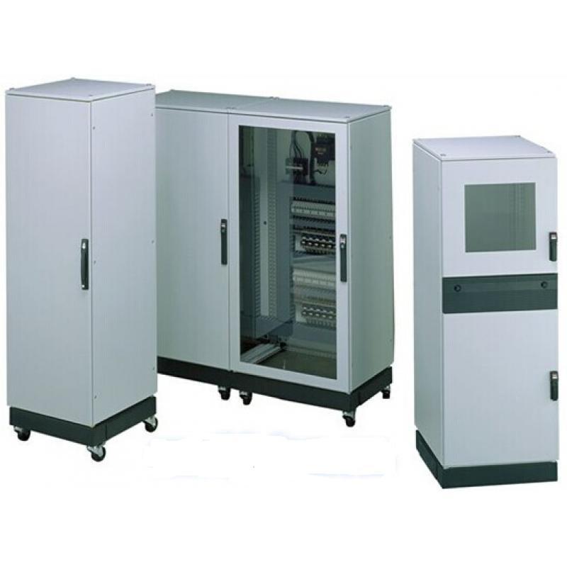
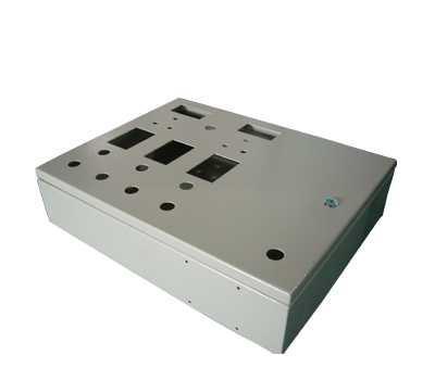
Surface Treatment Process of Chassis Cabinets 1. Alkaline Washing  After the chassis cabinet is formed, it is not truly completed; we still need to perform alkaline washing. Why do we need to do alkaline washing? The purpose is to remove the oil stains attached to the surface of the chassis cabinet. What alkaline washing liquid formulas do we often use? Generally, we use a combination of Na2CO3, Na3PO4, Na2SiO3, and additives. After alkaline washing, it is necessary to wipe with clean water to remove any residue of the alkaline solution.  2. Removal of Oxide Film  Generally speaking, the surface of the chassis cabinet's outer shell has a naturally formed oxide film that is usually uneven and a non-continuous film. When we paint the surface of the chassis cabinet, we must thoroughly remove it in advance. For die-cast parts, nitric acid can be used to treat the surface oxide film. After removing the oxide film, we also need to further treat it with clean water.  3. Chemical Conversion  After completing the previous steps, we also need to perform chemical conversion treatment. The purpose of this treatment is to form a dense, uniform, continuous film on the surface of the chassis cabinet. This process is actually equivalent to the phosphating process applied to the surface of steel parts, but it differs in that the solutions used are different. The conversion film of the electronic shell of the chassis machine is based on chromic acid/hydrochloric acid, phosphoric acid/hydrochloric acid, and hydrofluoric acid, with a typical conversion film quality of 215g/m2. After the conversion film is formed, it must be washed with clean water and then dried with hot air to enhance the hardness of the film layer.      The chassis cabinet products should have an aesthetically pleasing appearance, which means that appearance is very important. For chassis cabinet products, how to maintain the overall beauty of the chassis cabinet? In fact, to ensure that the overall beauty of the chassis cabinet lasts a long time, we need to put more effort into the surface treatment process of the chassis cabinet.       We can also provide customized services based on samples and drawings from customers, creating the styles and services you desire. The products are guaranteed in quality and quantity, while also providing you with a comfortable aesthetic enjoyment. Welcome to call for consultation and negotiation!

2021-12-30

Maintenance and Repair of CNC Machine Tools

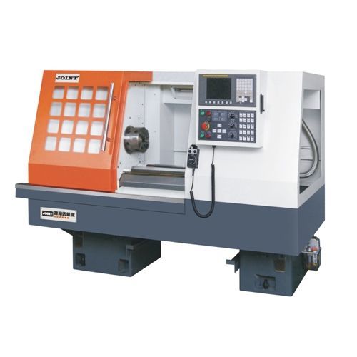
          Maintenance and Care of CNC Machine Tools The electrical maintenance and care of CNC machine tools is essential to fully realize their value and efficiency. Preventive maintenance must be performed to control CNC machine tool failures. When a failure occurs, it should be detected and repaired promptly to minimize maintenance time and costs. The main focus of preventive maintenance is to enhance daily maintenance, taking appropriate care measures based on different types of machine tools. 1. Maintenance of the CNC machine tool electrical system: (1) CNC machine tool equipment must be operated by specialized personnel according to the corresponding operating procedures and regulations. During operation, continuously improve the professional skills and qualities of the operators to technically reduce electromechanical failures. When electromechanical failures occur, operators should cooperate with relevant maintenance personnel to explain and discuss the issues, quickly identify problems, and eliminate faults;                                                                                                                                     (2) The CNC machine tool processing area must be kept clean and dry to avoid dust, metal powder, etc., from falling onto the machine body, causing corrosion, quality changes, and damage to the machine tool. Especially in summer, the CNC cabinet should not be opened, and appropriate cooling tools or programs must be used to prevent damage to the CNC system;                         (3) Avoid overheating of the CNC machine tool electrical system, and regularly maintain input and output devices. During work, it is necessary to strengthen the inspection of cooling fans, regularly check the operation of air duct filters, and promptly clean dust and particles. Regular maintenance and care of photoelectric readers should be conducted according to relevant regulations to prevent accidents;               (4) Regularly check the brushes of the DC motor. The brushes of the DC motor are important components of the CNC machine tool. Excessive wear of the DC motor can lead to performance issues and directly cause motor damage. Therefore, during the operation of the CNC machine tool, staff must regularly check the motor brushes to ensure the integrity of the machine tool components;   (5) Enhance the maintenance of spare circuit boards. In production, spare circuit boards must be regularly checked and maintained, allowing them to be installed in electromechanical equipment for preheating to avoid natural damage. 2. Improve the maintenance and care of mechanical components:  (1) Maintenance and care of the main rotating chain. Similarly, in daily life, staff must strengthen the adjustment of the spindle drive of the main rotating chain to prevent slippage that may cause loss of rotation; check and adjust the spindle lubrication temperature regularly; adjust the hydraulic cylinder piston of tools that have been running for a long time, and adjust the gap according to relevant regulations;     (2) Improve the maintenance and care of the tool library. Install tools of the corresponding specifications strictly according to installation regulations. Regularly conduct random inspections of the tool library to ensure it remains in the zero return position, and promptly improve the tool change position of the CNC machine tool spindle. Identify problems early and address them in a timely manner;                                 (3) Improve the maintenance and care of machine tool accuracy. Staff should regularly conduct random checks and calibrations of machine tool accuracy. Compensate system parameters according to accuracy calibration, such as: backlash compensation of the screw and calibration of the reference point position of the CNC machine tool, etc.; or conduct corresponding guide rail scraping during major repairs of the machine tool. 3. Maintenance technology for CNC machine tool failures   Troubleshooting of CNC machine tool failures includes: investigation, analysis, and handling of the CNC machine tool electrical system. The analysis process of electrical failures is the process of eliminating faults, so it must be combined with actual conditions and advanced technologies at home and abroad for subjective and objective maintenance and handling.   1. Visual inspection method. The visual inspection method is the primary method for analyzing CNC machine tool failures. Experienced technical maintenance personnel use sensory inspections and observations of abnormal phenomena such as light, smell, and sound at the time of failure to narrow down the fault.   2. Self-diagnosis function method. (1) Software alarm indication. For example: PLC programs and common alarm displays during processing, find fault elimination methods based on the data and descriptions of the alarm display; (2) Hardware alarm indication. Hardware alarm indication refers to the fault indicator lights and various statuses on the servo system and electronic and electrical devices within the CNC system, combined with the corresponding manuals to understand the fault types and elimination methods.   3. Parameter check method. The CNC machine tool control system is the core of the CNC machine tool, and parameters can connect various electrical systems and specific machine tools, maximizing the functionality of the entire machine tool. Protect parameter changes, adjust the machinery based on parameter changes, and try to keep the machine tool running in the best position. Therefore, maintenance personnel must be quite familiar with the parameters, understand the corresponding parameter addresses, and have rich debugging experience.   4. Exchange method and transfer method. The exchange method is based on analyzing the cause of the fault, using corresponding modules, printed circuit boards, integrated circuit chips, and components with suspected parts to narrow down the fault until reaching the printed circuit board level. The transfer method involves exchanging two printed circuit boards, modules, integrated chips, and components with similar performance to observe the fault transfer and determine the fault location.

2021-12-28

Key Points of Fixture Design

Key Points of Tooling Fixture Design The design of tooling fixtures is generally carried out after the machining process of the parts has been established, according to the specific requirements of a certain process. When formulating the process, the feasibility of the fixture should be fully considered, and if necessary, suggestions for modifications to the process can be made during the design of the tooling fixture. The quality of the tooling fixture design should be measured by its ability to stably ensure the machining quality of the workpiece, high production efficiency, low cost, convenient chip removal, safe and labor-saving operation, and ease of manufacturing and maintenance. I. Basic Principles of Tooling Fixture Design 1. Meet the stability and reliability of workpiece positioning during use; 2. Have sufficient bearing or clamping force to ensure the machining process of the workpiece on the tooling fixture; 3. Ensure simple and quick operation during clamping; 4. Easily worn parts must be structured for quick replacement, preferably without the need for other tools when conditions permit; 5. Ensure the reliability of repeated positioning during adjustment or replacement of the fixture; 6. Avoid complex structures and high costs as much as possible; 7. Preferably use standard parts as components; 8. Form a systematic and standardized internal product structure within the company. II. Basic Knowledge of Tooling Fixture Design A good machine tool fixture must meet the following basic requirements: 1. Ensure the machining accuracy of the workpiece. The key to ensuring machining accuracy lies in correctly selecting the positioning reference, positioning method, and positioning elements. If necessary, a positioning error analysis should be conducted, and attention should be paid to the impact of other components in the fixture on machining accuracy to ensure that the fixture meets the machining accuracy requirements of the workpiece. 2. Improve production efficiency. The complexity of special fixtures should be adapted to the production capacity. Various quick and efficient clamping mechanisms should be used as much as possible to ensure ease of operation, shorten auxiliary time, and improve production efficiency. 3. Good process performance. The structure of special fixtures should strive to be simple and reasonable, facilitating manufacturing, assembly, adjustment, inspection, and maintenance. 4. Good usability. Tooling fixtures should have sufficient strength and rigidity, and operation should be simple, labor-saving, and reliable. When conditions allow and are economically feasible, mechanical clamping devices such as pneumatic and hydraulic should be used as much as possible to reduce the labor intensity of the operator. Tooling fixtures should also facilitate chip removal. If necessary, a chip removal structure can be set up to prevent chips from damaging the positioning of the workpiece and damaging the tool, and to prevent chip accumulation from generating excessive heat that causes deformation of the process system. 5. Good economy. Special fixtures should use standard components and standard structures as much as possible, striving for simple structures and easy manufacturing to reduce the manufacturing cost of the fixture. Therefore, during the design process, a necessary technical and economic analysis of the fixture scheme should be conducted based on orders and production capacity to improve the economic benefits of the fixture in production. III. Overview of Standardization in Tooling Fixture Design 1. Basic methods and steps of tooling fixture design Preparation before design. The original data for tooling fixture design includes the following: a) Design notification, finished product drawings, blank drawings, and technical data such as process routes, understanding the machining technical requirements of each process, positioning and clamping schemes, machining content of previous processes, blank conditions, machine tools, tools, inspection gauges used in machining, machining allowances, and cutting amounts; b) Understand the production batch and the need for fixtures; c) Understand the main technical parameters, performance, specifications, accuracy of the machine tools used, and the connection dimensions of the fixture; d) Inventory status of standard materials for fixtures. 2. Issues to consider in tooling fixture design Fixture design generally has a simple structure, giving the impression that the structure is not very complex, especially with the prevalence of hydraulic fixtures, which greatly simplifies the original mechanical structure. However, if detailed consideration is not given during the design process, unnecessary troubles will inevitably arise: a) The blank allowance of the workpiece. If the blank size is too large, interference will occur. Therefore, a blank drawing must be prepared before design, leaving enough space. b) The chip removal smoothness of the fixture. Due to the limited machining space of the machine tool, fixtures are often designed to be compact, which may overlook the accumulation of chips in the dead corners of the fixture during the machining process, including the poor outflow of cutting fluid, causing many troubles in subsequent machining. Therefore, issues that may arise during the machining process should be considered from the beginning, as fixtures are designed to improve efficiency and facilitate operation. c) The overall openness of the fixture. Neglecting openness can make it difficult for operators to load and unload, wasting time and effort, which is a major design taboo. d) The basic theoretical principles of fixture design. Each fixture must undergo countless clamping and releasing actions, so it may initially meet user requirements, but the fixture should maintain its precision. Therefore, do not design anything that contradicts principles. Even if it works at the moment, it will not have long-term sustainability. A good design should withstand the test of time. e) The replaceability of positioning elements. Positioning elements wear out severely, so quick and convenient replacement should be considered. It is best not to design them as large parts. Accumulating experience in fixture design is important. Sometimes design is one thing, and practical application is another, so good design is a process of continuous accumulation and summarization. Commonly used tooling fixtures are mainly divided into the following types based on functionality: 01 Clamping Molds 02 Drilling and Milling Fixtures 03 CNC and Instrument Chucks 04 Air Testing and Water Testing Fixtures 05 Punching and Shearing Fixtures 06 Welding Fixtures 07 Polishing Jigs 08 Assembly Fixtures 09 Transfer Printing and Laser Engraving Fixtures 01 Clamping Molds Definition: Tools used for positioning and clamping based on the product's external shape. Design Points: 1. This type of clamping mold is mainly used on a vise, and its length can be cut according to needs; 2. Other auxiliary positioning devices can be designed on the clamping mold, generally connected by welding; 3. The above image is a simplified diagram, and the mold cavity structure dimensions are determined by specific conditions; 4. A positioning pin with a diameter of 12 should be tightly fitted at an appropriate position on the moving mold, and the positioning hole at the corresponding position of the fixed mold should be a sliding fit with the positioning pin; 5. The assembly cavity should be designed to offset and enlarge by 0.1mm based on the outer shape of the non-shrinking blank drawing. 02 Drilling and Milling Fixtures Design Points: 1. If necessary, some auxiliary positioning devices can be designed on the fixed core and its fixed plate; 2. The above image is a structural diagram, and the actual situation should be designed according to the product structure; 3. The cylinder size is determined based on the product size and the force situation during processing, commonly using SDA50X50; 03 CNC and Instrument Chucks A. CNC Chucks Internal Conical Chucks Design Points: 1. The dimensions not marked in the above image are based on the actual internal hole size of the product; 2. The outer circle that contacts the internal hole of the product should leave a single-sided allowance of 0.5mm during production, and finally be precision turned to size on the CNC machine to prevent deformation and eccentricity caused by the quenching process; 3. The material for the assembly part is recommended to be spring steel, and the pull rod part is 45#; 4. The thread of the pull rod part is M20, which is a commonly used thread and can be adjusted according to actual conditions. Instrument Internal Conical Chucks Design Points: 1. The above image is a reference diagram, and the assembly dimensions and structure are based on the actual external dimensions of the product; 2. The material used is 45#, with quenching treatment. Instrument External Conical Chucks Design Points: 1. The above image is a reference diagram, and the actual dimensions are based on the internal hole size structure of the product; 2. The outer circle that contacts the internal hole of the product should leave a single-sided allowance of 0.5mm during production, and finally be precision turned to size on the instrument lathe to prevent deformation and eccentricity caused by the quenching process; 3. The material used is 45#, with quenching treatment. 04 Air Testing Fixtures Design Points: 1. The above image is a reference diagram for air testing fixtures, and the specific structure should be designed based on the actual structure of the product. The idea is to seal the product in the simplest way possible, allowing the part that needs to be tested for sealing to be filled with gas to confirm its sealing performance; 2. The size of the cylinder can be adjusted according to the actual size of the product, and it should also consider whether the cylinder stroke can facilitate the easy loading and unloading of the product; 3. The sealing surface that contacts the product generally uses materials with good compressibility, such as polyurethane and NBR rubber rings. Also, if there are positioning blocks that contact the product's appearance, try to use white plastic blocks and cover them with cloth during use to prevent damage to the product's appearance; 4. The design should consider the positioning direction of the product to prevent internal leakage of gas from being trapped inside the product cavity, leading to misdetection. 05 Punching Fixtures Design Points: The above image shows the common structure of punching fixtures. The base plate serves to facilitate fixing on the workbench of the punching machine; the positioning block serves to fix the product, and the specific structure is designed according to the actual situation of the product, with the center point arranged to facilitate safe loading and unloading of the product; the baffle serves to facilitate the product's separation from the punch; the support pillar serves to fix the baffle. The assembly positions and dimensions of the above parts can be designed according to the actual situation of the product. 06 Welding Fixtures Welding fixtures mainly serve to fix the positions of various components in the welding assembly and control the relative dimensions of the components in the welding assembly. Their structure mainly consists of positioning blocks, which need to be designed according to the actual structure of the product. It is worth noting that when the product is placed on the welding fixture, no sealing space should be created between the fixtures to prevent excessive pressure in the sealing space during the welding heating process, affecting the dimensions of the components after welding. 07 Polishing Jigs 08 Assembly Fixtures Assembly fixtures are mainly used as auxiliary positioning devices during the assembly process of components. The design idea is to facilitate the easy loading and unloading of products based on the structure of the component assembly, ensuring that the product's appearance surface is not damaged during the assembly process, and allowing for the covering of cotton cloth during use to protect the product. In terms of material selection, non-metallic materials such as white glue should be used as much as possible. 09 Transfer Printing and Laser Engraving Fixtures Design Points: The positioning structure of the fixture should be designed according to the actual engraving requirements of the product, paying attention to the convenience of loading and unloading the product and protecting the product's appearance. Positioning blocks and auxiliary positioning devices that contact the product should use non-metallic materials such as white glue as much as possible.

2021-12-27

Tips for processing internal threads

        Tips for Internal Thread Processing Expansion of Internal Thread Middle Diameter Improper Selection of Taps 1. Use taps suitable for precision grade 2. Increase the length of the entry section 3. Reduce the front angle 4. Choose taps with a concentric wide flat back 5. Adjust the back angle of the cutting cone length Chip Blockage 1. Use a tapered tap or spiral tap 2. Reduce the number of flutes on the tap while increasing the flute volume 3. Use fine thread 4. Maximize the diameter of the blind hole 5. Deepen the bottom hole as much as possible in the case of blind holes 6. Shorten the tapping length 7. Change to a different type of cutting oil and oiling method 8. Choose internal cooling taps Improper Working Conditions 1. Adjust cutting speed 2. Prevent the tap from being eccentric or tilted with the bottom hole 3. Change the fixation of the tap or workpiece to a floating type 4. The feed speed should be appropriate to prevent deformation of the thread crest 5. Use a forced feeding method (pitch feeding method) 6. Appropriately select the processing capacity of the tapping machine 7. Prevent spindle vibration 8. Use flexible taps Adhesion 1. Use taps with surface oxidation treatment 2. Change to cutting oil with higher anti-welding properties 3. Reduce cutting speed 4. Change cutting angles to suit the material being cut 5. Choose internal cooling taps 6. Shorten the length of the threaded section Reduction of Internal Thread Middle Diameter Improper Selection of Taps 1. Use larger taps A. For materials like copper alloys, aluminum alloys, cast iron, etc., the tapping expansion rate is less B. For materials that are tubular or thin plates, etc., which are prone to rebound 2. The entry clearance angle should be appropriate 3. Increase the cutting angle 4. Increase the front angle 5. Increase the number of flutes External Damage to Internal Threads When retracting, especially when the tap is about to leave the internal thread mouth, the speed should be appropriate to avoid damage Residual Chips in Internal Threads 1. Increase the sharpness of the tap to reduce the residual hair-like chips 2. Only check the internal thread with gauges after completely removing the residual chips Chipping or Scoring Insufficient Entry Section Length 1. Increase the length of the entry section at the tip 2. Improper cutting angle 3. The cutting angle must match the material of the workpiece Adhesion 1. Use taps with clearance angles in the threaded section 2. Reduce the thickness of the cutting edge 3. Use taps that have been surface treated 4. Change the type of cutting oil and oiling method 5. Reduce cutting speed Chip Blockage 1. Use a tapered tap or spiral tap 2. Increase the diameter of the bottom hole Vibration Excessively Sharp 1. Reduce the cutting angle 2. Grind down the clearance angle between the threaded sections Improper Regrinding 1. Avoid making the cutting edge thickness too small 2. Do not grind the bottom of the flutes 3. Issues related to the durability of the taps Tap Breakage Chip Blockage 1. Replace the tap material 2. Prevent iron chips from blocking (or use tapered taps, spiral taps, or chipless taps) 3. Increase the chip space 4. Clear chips around the bottom hole and workpiece 5. Ensure the chip removal space is clear Excessive Cutting Torque 1. Maximize the diameter of the bottom hole 2. Shorten the tapping length 3. Change to fine thread 4. Increase the cutting angle to enhance the sharpness of the tap 5. To reduce friction, torque, and the clearance angle of the threaded section, slightly increase the clearance angle and reduce the thickness of the cutting edge 6. Use spiral taps Improper Working Conditions 1. Reduce cutting speed 2. Prevent the tap from being eccentric or tilted with the bottom hole 3. Use floating type for tap clamping 4. Change the tapping clamp to an adjustable type 5. For non-through bottom holes, prevent the tap from hitting the bottom of the hole 6. Prevent work hardening of the bottom hole during processing 7. Maintain stable feeding 8. Remove iron chips generated from the previous process 9. Investigate the hardness and uniformity of the material being processed Improper Regrinding 1. Do not grind the bottom of the flutes 2. Avoid making the cutting edge thickness too small 3. Worn parts should be ground off 4. Regrind earlier Cutting Edge Chipping Improper Selection of Taps 1. Reduce the cutting angle 2. Change the material of the tap 3. Reduce hardness 4. Lengthen the entry section 5. Prevent chip blockage (should use spiral taps) 6. Shorten the length of the thread 7. Completely remove worn parts 8. Avoid making the cutting edge thickness too small Improper Working Conditions 1. Reduce cutting speed 2. Prevent center deviation, avoid imbalance during entry 3. For non-through holes, do not rotate rapidly 4. Increase the length of the entry section 5. Use flexible tapping fixtures 6. Improve coaxiality 7. Prevent work hardening during processing of the bottom hole.

2021-12-23

The requirement for a stable structure of the sheet metal chassis shell.

                      The requirement for the structural stability of the sheet metal chassis shell   The rapid development of the sheet metal processing industry has promoted the construction of socialist modernization, and the normal operation of a large number of public facilities relies on the contributions of the sheet metal processing industry. With the further development of sheet metal chassis shells, the types of chassis shells have become diverse according to different application areas and their functional focuses. However, generally speaking, the more popular chassis shells on the market are still the standard chassis shells, indoor cabinets, outdoor cabinets, etc.           Sheet metal chassis shells are specifically designed to house some electronic devices that can provide services for us. Therefore, it is very important for these devices to be secured.   The design of the sheet metal chassis shell is to meet the usage requirements of the devices. Nowadays, there are more and more devices, and the manufacturing requirements for chassis shells are becoming increasingly high. A larger chassis shell facilitates installation and maintenance, and various sizes and components of chassis shells can be flexibly configured according to different application needs, enhancing the usability of the chassis shell, making it simple and convenient.   Heavy steel materials can ensure the sturdiness of the chassis shell, and they can also enhance its load-bearing capacity. A good load-bearing structure is essential to ensure the normal application of the chassis shell. Often, the allocation of space in the internal structure is very important. If the actual requirements do not demand excessive space, we can arrange the internal devices more compactly. This does not affect the load-bearing structure.                                                                            It is undeniable that the chassis shell products emphasize practicality, and the choice of materials is fundamental:    1. Whether the corner connections of the sheet metal chassis shell are smooth and flat, without defects or gaps;    2. Check whether the surface of the chassis shell has burrs or protrusions, whether the appearance is smooth, flat, with uniform color, and whether the spray coating is firm and even;   3. From the surface, the aluminum-zinc cabinet usually consists of a base, top cover, and panel, with the main material made of aluminum-zinc steel plate.

2021-12-21

Chassis Electrical Cabinet Assistant - Laser Cutting Machine

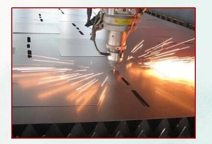
                                Chassis Electrical Cabinet Assistant - Laser Cutting Machine The computers we often use in our daily work, the cabinets we frequently encounter in life, the electrical cabinets at home, and the safe cabinets are all types of metal cabinets. Although this cabinet may seem unremarkable, it plays an important role. Do you know how this cabinet has become what it is today? Below, the editor will take you to learn more about it in detail. Chassis Cabinet Assistant - Laser Cutting Machine   The chassis cabinet refers to cabinets made through sheet metal processing equipment. Manufacturers of computer chassis, server room equipment, safe cabinets, and distribution cabinets choose to use laser cutting equipment for its stability, speed, and high precision, which completely eliminates the need for secondary processing of workpieces, greatly improving production efficiency and reducing production costs. At the same time, due to the increasingly fierce market competition in the chassis cabinet industry, products with multiple varieties and small batches are becoming more popular in the market. The flexible processing method of laser cutting greatly improves product quality while significantly shortening the research and development production cycle, providing customers with strong competitiveness. Laser cutting replaces traditional mechanical blades with "beams," allowing for fast cutting speeds and smooth edges, generally without the need for post-processing. Laser cutting is suitable for almost all types of metal materials, whether simple or complex parts, and can be precisely and quickly formed in one go. By using software for drawing in conjunction with cutting work, there is no need for molds, which not only enables product diversification but also greatly reduces mold costs. The expert in chassis cabinet processing - Laser Cutting Machine Advantages of metal laser cutting machines in chassis electrical cabinet processing: Non-contact processing, no direct impact on workpieces, thus no mechanical deformation; No "tool" wear during the laser cutting process, saving costs; During the laser cutting process, the energy density of the laser beam is high, processing speed is fast, and it is localized processing, with minimal or no impact on non-laser irradiated areas, thus reducing thermal influence and thermal deformation of workpieces;   Because the laser beam is easy to guide, focus, and change direction, it easily cooperates with numerical control systems to process complex workpieces, making it an extremely flexible processing method; high production efficiency, stable and reliable processing quality, and good economic and social benefits.   Traditional sheet metal processing techniques include plasma cutting, flame cutting, and punching, but traditional processing techniques can no longer meet people's aesthetic requirements. Nowadays, laser cutting has been widely used in sheet metal processing. On one hand, the processing efficiency and speed of laser cutting machines are fast; on the other hand, the samples cut by laser cutting machines are as smooth as a mirror and do not require secondary processing, which is also beneficial for the sales of sheet metal manufacturers. Therefore, laser cutting machines are applied to chassis cabinet cutting.

2021-12-18

How to Become a "Master Operator" of CNC Machine Tools

  How to Become a "Master Operator" of CNC Machine Tools Currently, among many newly engaged CNC machine tool operators in China,   some operators are very familiar with mechanical processing but are relatively unfamiliar with CNC machine programming; some are recent graduates who are familiar with the theoretical knowledge of mechanical processing, CNC processing, and programming but lack practical mechanical processing experience; there are also many operators who have never been exposed to mechanical processing and programming, making it extremely difficult for them to learn CNC machine operation. For these beginners in CNC machine tools, mastering certain CNC machine operation skills is very important. On one hand, they can avoid machine collision accidents that lead to machine damage; on the other hand, they can quickly improve the operator's CNC machine operation skills in a short period, enabling them to perform their job competently. This article specifically introduces some theoretical knowledge of CNC machine operation skills for those who have just come into contact with CNC machine tools, hoping to provide some reference for newly engaged CNC machine operators. Key Point 1: Operators need to have a comprehensive understanding of the CNC machine tool they are operating. Understand the mechanical structure of the machine: Understand the mechanical composition of the machine; master the distribution of the machine's axis system; firmly grasp the positive and negative directions of each CNC axis of the machine; understand the functions and uses of each component of the machine, such as the principles and functions of simple pneumatic systems, and the working principles and functions of simple hydraulic systems; additionally, understand the working principles and functions of various auxiliary units of the machine, such as tool changers, cooling units, voltage stabilizers, electrical cabinet coolers, etc., as well as the working principles, functions, and usage methods of each safety door lock of the machine. Firmly grasp the functions of each operation button of the machine: Know how to execute programs; how to pause the program, check the workpiece processing status, and then resume the paused state to continue executing the program; how to stop the program; how to change the program and then execute it, and so on. Understand what kind of operating system your machine uses; have a basic understanding of the control principles and working methods of the CNC system; what kind of working language the system uses, the software used for machine processing, and the language it uses. If the operator is unfamiliar with this language or its technical vocabulary, then professional training is needed. During training, it is essential to take notes carefully, understanding what each term in the machine software represents in Chinese, and memorizing it thoroughly to ensure correct usage of the machine in future work. Key Point 2: Be proficient in manual or automatic operation of the CNC machine tool, and master the movement of each CNC axis of the machine. Operators must reach a level of proficiency where they can handle the machine skillfully in any situation; they should be able to correctly and promptly address issues when encountering collisions or faults, forming a conditioned reflex to decisively take braking measures. Additionally, operators must be very familiar with the processing programs of the CNC machine; they should know what kind of actions the machine should perform for each process and operation. When the machine executes a program, they should be able to immediately determine whether the machine's actions are correct and whether braking measures need to be taken. Furthermore, every beginner operator may have some fear during the initial operation of the machine, fearing collisions or machine crashes. Only after the operator has mastered the operation of the CNC machine can they overcome such fears and build upon that foundation to learn more advanced CNC machine operation skills. Third, be proficient in program editing, parameter compensation for each process, and compensation for the diameter and length of tools or grinding wheels. First, after training, master the programming language, programming methods, and parameter compensation methods for the CNC machine you will operate. Most advanced CNC machines are now equipped with programming or simulation PC workstations. Therefore, beginners can first conduct software editing and machine cutting simulation learning on the workstation. Key Point 4: Processing skills during the actual processing process, carefully prepare in advance, first understand the drawings, confirm the position of the workpiece to be processed, and confirm the precision tolerances of the parts to be processed, and then edit the processing program. Prepare the workpieces and tools or grinding wheels needed for processing, prepare the measuring instruments needed during the processing, and ensure that all auxiliary tools and fixtures needed during the processing are ready.

2021-12-16

The process flow of gear processing for laser marking machines

    The process flow of laser marking machine gear processing Everyone knows that gears are the most widely used general mechanical parts in the transmission systems of mechanical equipment. Traditionally, carburizing processes and high-frequency surface hardening processes are mainly used, employing low-carbon steel materials to give the workpiece surface wear resistance. This process has good comprehensive performance, but due to high costs, potential environmental pollution, and inconvenience in handling large modulus gears and large gear shafts, it is currently only used in specific industries such as automobiles and tractors. With the continuous improvement of random laser marking machine technology, gears are widely used in mechanical equipment and effectively solve the above problems. The gear laser marking machine applies advanced 3D dynamic marking technology, allowing marking on surfaces that are not on the same plane by setting different heights in the software. Its maximum marking speed of 7000mm/s with high-speed galvanometer scanning is suitable for industrial mass production. Additionally, it uses a fully enclosed optical path, imported CO2 radio frequency laser, and a strict multi-protection control design to ensure the overall stability of the equipment. Product advantages: 1. Fully enclosed maintenance-free laser optical system, no need for adjustment, plug and play, high precision, and high-speed marking/cutting performance, with work efficiency improved by 20% compared to similar models. 2. Original imported coherent radio frequency laser from the USA, high power, good spot quality, stable power, and a lifespan of over 20,000 hours. 3. A professional constant temperature circulating industrial cooling water system makes the entire machine run more stably and consume less power, with a strict multi-protection control design suitable for a wide range of environmental temperatures, ensuring the laser marking system operates reliably for 24 hours.

2021-12-14

24 Common Metal Materials and Their Properties

   24 Common Metal Materials and Their Characteristics 1. 45 - High-quality carbon structural steel, the most commonly used medium carbon quenched and tempered steel Main Features: The most commonly used medium carbon quenched and tempered steel, with good comprehensive mechanical properties, low hardenability, and prone to cracking during water quenching. Small parts should be treated with quenching and tempering, while large parts should be treated with normalizing. Application examples: Mainly used for manufacturing high-strength moving parts, such as turbine impellers, compressor pistons, shafts, gears, racks, worm gears, etc. For welded parts, preheat before welding and stress relief annealing after welding. 2. Q235A (A3 steel) - The most commonly used carbon structural steel Main Features: High plasticity, toughness, and welding performance, cold stamping performance, as well as certain strength and good cold bending performance. Application examples: Widely used for parts and welded structures with general requirements, such as low-stress tie rods, connecting rods, pins, shafts, screws, nuts, sleeves, brackets, machine bases, building structures, bridges, etc. 3. 40Cr - One of the most widely used steel grades, belonging to alloy structural steel Main Features: After quenching and tempering, it has good comprehensive mechanical properties, low-temperature impact toughness, and low notch sensitivity, good hardenability, high fatigue strength when oil cooled, and prone to cracking in complex-shaped parts when water cooled. Cold bending plasticity is moderate, good machinability after tempering or quenching and tempering, but poor weldability, prone to cracking, preheat to 100-150°C before welding, generally used in the quenched and tempered state, and can also undergo carbon-nitrogen co-infiltration and high-frequency surface hardening treatment. Application examples: After quenching and tempering, used for manufacturing medium-speed, medium-load parts, such as machine tool gears, shafts, worm gears, spline shafts, ejector sleeves, etc. After quenching and high-frequency surface hardening, used for manufacturing parts with high surface hardness and wear resistance, such as gears, shafts, spindles, crankshafts, center shafts, sleeves, pins, connecting rods, screws, nuts, intake valves, etc. After quenching and medium-temperature tempering, used for manufacturing heavy-load, medium-speed impact parts, such as oil pump rotors, sliders, gears, spindles, sleeves, etc. After quenching and low-temperature tempering, used for manufacturing heavy-load, low-impact, wear-resistant parts, such as worm gears, spindles, shafts, sleeves, etc. Carbon-nitrogen co-infiltration parts are used for manufacturing larger-sized, high low-temperature impact toughness transmission parts, such as shafts, gears, etc. 4. HT150 - Gray cast iron Application examples: Gearbox housings, machine tool beds, boxes, hydraulic cylinders, pump bodies, valve bodies, flywheels, cylinder heads, pulleys, bearing covers, etc. 5. 35 - Common materials for various standard parts and fasteners Main Features: Appropriate strength, good plasticity, high cold plasticity, and acceptable weldability. Can be locally forged and drawn in the cold state. Low hardenability, used after normalizing or quenching and tempering. Application examples: Suitable for manufacturing small cross-section parts that can withstand larger loads, such as crankshafts, levers, connecting rods, hooks, and various standard parts and fasteners. 6. 65Mn - Common spring steel Application examples: Various small flat and round springs, seat cushion springs, spring coils, can also be made into spring rings, valve springs, clutch spring plates, brake springs, cold coiled spiral springs, snap rings, etc. 7. 0Cr18Ni9 - The most commonly used stainless steel (American steel grade 304, Japanese steel grade SUS304) Characteristics and Applications: The most widely used stainless and heat-resistant steel, such as food equipment, general chemical equipment, and equipment used in the energy industry. 8. Cr12 - Common cold work die steel (American steel grade D3, Japanese steel grade SKD1) Characteristics and Applications: Cr12 steel is a widely used cold work die steel, belonging to high carbon high chromium type ledeburite steel. This steel has good hardenability and wear resistance; due to the high carbon content of Cr12 steel reaching 2.3%, its impact toughness is poor, prone to brittle fracture, and easily forms uneven eutectic carbides; Cr12 steel is widely used for manufacturing cold stamping dies, punches, blanking dies, cold heading dies, cold extrusion dies, and other dies that require high wear resistance but are subjected to low impact loads. 9. DC53 - Commonly used Japanese imported cold work die steel Characteristics and Applications: High-strength and tough cold work die steel, produced by Daido Steel Co., Ltd. in Japan. After high-temperature tempering, it has high hardness and toughness, and good wire cutting performance. Used for precision cold stamping dies, stretching dies, wire drawing dies, cold stamping dies, punches, etc. 10. SM45 - General carbon plastic mold steel (Japanese steel grade S45C) 11. DCCr12MoV - Wear-resistant chromium steel Domestic. Lower carbon content than Cr12 steel, and added Mo and V, improving the unevenness of carbides. Mo can reduce carbide segregation and improve hardenability, while V can refine grains and increase toughness. This steel has high hardenability, can be fully hardened with a cross-section below 400mm, and maintains good hardness and wear resistance at 300-400°C. Compared to Cr12, it has higher toughness, small volume change during quenching, high wear resistance, and good comprehensive mechanical properties. Therefore, it can manufacture various molds with large cross-sections and complex shapes that can withstand large impacts, such as ordinary stretching molds, punching dies, blanking dies, cutting dies, rolling dies, wire drawing dies, cold extrusion dies, cold cutting scissors, circular saws, standard tools, measuring tools, etc. 12. SKD11 - Tough chromium steel Produced by Hitachi Ltd. in Japan. Technically improves the casting structure in the steel, refines the grains. Toughness and wear resistance are improved compared to Cr12mov. Extends the service life of the molds. 13. D2 - High carbon high chromium cold work steel Produced in the USA. Has high hardenability, hardenability, wear resistance, good high-temperature oxidation resistance, good rust resistance after quenching and polishing, small thermal treatment deformation, suitable for manufacturing various high-precision, long-life cold work molds, cutting tools, and measuring tools, such as stretching molds, cold extrusion molds, cold shear knives, etc. 14. SKD11 (SLD) - Non-deforming high toughness chromium steel Produced by Hitachi Ltd. in Japan. Due to the increased content of Mo and V in the steel, it improves the casting structure in the steel, refines the grains, and improves the carbide morphology, thus this steel's toughness (bending strength, deflection, impact toughness, etc.) is higher than SKD1 and D2, and wear resistance is also increased, with higher tempering resistance. Practice has proven that the service life of this steel mold is improved compared to Cr12mov. Commonly used for manufacturing high-demand molds, such as stretching molds, impact grinding wheel molds, etc. 15. DC53 - High toughness high chromium steel Produced by Daido Steel Co., Ltd. in Japan. The hardness after heat treatment is higher than SKD11. After high-temperature (520-530°C) tempering, it can reach 62-63HRC high hardness, and in terms of strength and wear resistance, DC53 exceeds SKD11. The toughness of DC53 is twice that of SKD11. The toughness of DC53 rarely shows cracks and crazing in cold work mold manufacturing, greatly improving the service life. Residual stress is small. High-temperature tempering reduces residual stress. Cracks and deformations after wire cutting processing are suppressed. Cutting and grinding performance exceed SKD11. Used for precision stamping dies, cold forging, deep drawing molds, etc. 16. SKH-9 - General-purpose high-speed steel with wear resistance and toughness Produced by Hitachi Ltd. in Japan. Used for cold forging molds, cutting machines, drill bits, reamers, punches, etc. 17. ASP-23 - Powder metallurgy high-speed steel Produced in Sweden. Carbide distribution is extremely uniform, wear-resistant, high toughness, easy to process, and heat treatment size stability. Used for punches, deep drawing molds, drill molds, milling cutters, and various long-life cutting tools. 18. P20 - General requirement size plastic molds Produced in the USA. Can be used for electrical erosion operations. Factory state pre-hardened HB270-300. Quenching hardness HRC52. 19. 718 - High requirement size plastic molds Produced in Sweden. Especially for electrical erosion operations. Factory state pre-hardened HB290-330. Quenching hardness HRC52. 20. Nak80 - High mirror, high precision plastic molds Produced by Daido Steel Co., Ltd. in Japan. Factory state pre-hardened HB370-400. Quenching hardness HRC52. 21. S136 - Corrosion-resistant and mirror-polished plastic molds Produced in Sweden. Factory state pre-hardened HB<215. Quenching hardness HRC52. 22. H13 - Commonly used die-casting molds Used for aluminum, zinc, magnesium, and alloy die casting. Hot stamping molds, aluminum extrusion molds. 23. SKD61 - High-grade die-casting molds Produced by Hitachi Ltd. in Japan, using electric arc remelting technology, significantly improving service life compared to H13. Hot stamping molds, aluminum extrusion molds. 24. 8407 - High-grade die-casting molds Produced in Sweden. Hot stamping molds, aluminum extrusion molds. 25. FDAC - Added sulfur to enhance machinability Factory pre-hardened hardness 338-42HRC, can be directly processed for engraving, no need for quenching and tempering. Used for small batch molds, simple molds, various resin products, sliding parts, and molds with short delivery times. Zipper molds, eyeglass frame molds.

2021-12-11

Issues to pay attention to in sheet metal design

A. Bending interference issues; B. Minimum bend edge: not less than 4 times the plate thickness; going below this limit may greatly increase processing difficulty, or even make processing impossible. C. Deformation of holes caused by bending: holes too close to the bending line may be deformed by the mold. Since bending often needs to be determined based on actual conditions, maintaining necessary communication with process engineers can greatly improve design efficiency. 3. General Punching Where possible, standardize and unify to reduce mold costs and shorten sampling cycles. 4. Fitting Counterbore: It should be noted that the plate thickness should not be less than the height of the countersunk screw head; otherwise, the screw head will protrude above the plate, leading to an insecure fixation. 5. Riveting 5.1 When the plate thickness is less than 1mm, it may lead to easy detachment of the riveted parts; at this time, expanding rivets or welding after riveting can be used to ensure fastening strength. 5.2 The relationship between rivet screws and plate thickness Image 5.3 If the riveted part is too close to the edge, it will produce two consequences: A. The edge of the plate will deform after riveting (the edge will bulge), and the hole position will shift 0.1-0.5mm towards the edge; B. If the riveting position is too close to the bend edge, the upper mold cannot be pressed down: the distance from the outer edge of the riveting head to the bend edge should be no less than 3mm. 5.4 For U-shaped bent parts, the inner side riveting should consider whether the lower riveting mold can fit the workpiece; for other workpieces with relatively narrow internal spaces that require inner side riveting, this issue should be taken into account. 5.5 The specifications of riveted parts should be as uniform as possible to facilitate supplier ordering, shorten sampling cycles, and reduce the probability of errors in riveted parts. 6. Welding 6.1 For workpieces with relatively narrow internal spaces that require inner side welding, consideration should be given to how the welding gun can be inserted. 6.2 When the plate thickness is ≤1mm, it is easy to produce shrink holes or burn-through after welding, and the deformation caused by welding is relatively large. 6.3 Welding of materials such as copper and aluminum is more difficult and requires a higher skill level from welders. 7. Spraying Spraying is mainly divided into the following three types (each includes indoor and outdoor): Flat: can be subdivided into matte, flat, and glossy; the spraying layer thickness is about 60-90μm, and after recoating, it is about 90-120μm. Sand texture: can be subdivided into fine sand texture and coarse sand texture; the spraying layer thickness is about 50-80μm, and after recoating, it is about 80-110μm. Orange peel: can be subdivided into small orange peel and large orange peel; the spraying layer thickness is about 90-120μm, and after recoating, it is about 120-150μm. The spraying layer thickness in areas prone to powder accumulation will exceed the above thickness. 7.1 Flat: Advantages: aesthetically pleasing appearance, good silk screen effect; Disadvantages: high spraying cost, high rework rate, easily scratched, and surface scratches cannot be repaired, with glossy spraying being the most difficult. Avoid using flat finishes where possible, especially for large enclosures, as they are prone to bumps during handling. 7.2 Sand texture: Advantages: not easily scratched, spraying cost is the lowest among the three; Disadvantages: surface oil stains are not easy to remove, and silk screen effect is not as good as flat or orange peel. 7.3 Orange peel: Advantages: not easily scratched, good silk screen effect, surface oil stains are easy to remove, spraying cost is slightly higher than sand texture but far lower than flat. Disadvantages: aesthetic level is slightly lower than flat. 7.4 Spraying colors should be as uniform as possible, using the colors of the company's mainstream products to facilitate supplier ordering of powders. 7.5 A product should ideally use only one spraying color to reduce spraying costs (using multiple colors greatly increases processing time) and also reduce the probability of supplier spraying errors. 7.6 Avoid using silver powder. Silver powder contains silver compounds, and the price of the powder is twice that of ordinary powder, with greater spraying difficulty, leading to a higher likelihood of defects.

2021-12-10

The impact of temperature on Size measurement

              The Impact of Temperature on Measurement Size We conduct a large number of various measurements every day, striving for measurement accuracy during the process. Today, we will briefly discuss the impact of temperature on length measurement. 1. Factors Affecting Temperature Error In measurement conditions, factors such as temperature, humidity, vibration, dust, and corrosive gases can directly or indirectly affect measurement accuracy. Among these factors, the variation in temperature has a particularly significant impact on measurement accuracy. Due to the large differences in the expansion coefficients of different materials, the principle of equalizing the temperature of the measured object with that of the measuring standard instrument is adopted during measurement. Various measurement professions should work according to the temperature conditions required by the verification procedures to ensure the accuracy of the detection data. Currently, the standard temperature for measurement rooms in our country is set at 20℃. By consulting the manual, the relationship between the linear expansion coefficient a, temperature change, and size change can be expressed as follows: In the formula: a is the linear expansion coefficient; △L is the size change; L is the object size; △T is the temperature change. When a workpiece experiences size changes due to its temperature deviating from 20℃, it can be expressed as: In the formula: t is the temperature of the object. When both the workpiece and the measuring tool have deviations from the standard temperature, the measurement error caused by temperature is the difference in size changes of the two, which can be expressed as: In the formula: △L is the size change; L is the object size; a1 and a2 are the linear expansion coefficients of the workpiece and measuring tool materials; t1 and t2 are the temperatures of the workpiece and measuring tool. Definition of the linear expansion coefficient of an object: The size change of a unit length (1mm) when the temperature changes by 1℃ is only related to the material of the object. Example: Suppose a micrometer measures a copper shaft with a diameter of ∅100mm, where the shaft's temperature is 40℃ and the micrometer's temperature is 15℃. The linear expansion coefficients of the copper shaft and the steel micrometer are 17.5 x10⁻⁶ and 11.5 x10⁻⁶, respectively. The size change △L is: It can be seen that temperature has a significant impact on the size of the workpiece, with this example showing a difference of several tens. Therefore, when measuring measuring instruments, it is necessary to measure after the workpiece and measuring tool have reached thermal equilibrium, which will greatly reduce temperature errors. The time required for temperature balancing during the verification of each measuring tool is specified in the corresponding verification procedures and calibration specifications. Note: The process in which the temperature of the measured tool and the standard tool tends to be consistent under certain conditions (such as at room temperature of (20±6)℃) is called thermal equilibrium. 2. Methods to Reduce Temperature Errors 1. Measure when the temperature is close to the standard temperature. In actual work, we also strictly follow relevant procedures, ensuring that the measuring instruments sent by customers reach thermal equilibrium with the measurement room temperature before verification or calibration. Therefore, if customers want to obtain measurement data immediately, the data will definitely be affected by temperature. 2. When measuring on-site, do not take out the standard instrument and measure immediately. Instead, place the standard instrument and the workpiece together, and let them reach thermal equilibrium on a large flat surface before measuring. 3. Avoid the influence of hand temperature on the workpiece and measuring tool. For example, when using and verifying the micrometer, it is necessary to hold it with an insulating pad. When it is found that the heat from the hand has been transferred to the micrometer, it should be placed aside for a certain period before use and verification. 4. When measuring large sizes outdoors, it is necessary to use measuring instruments for temperature compensation according to the corresponding materials to minimize temperature errors.

2021-12-07

How to ensure the quality of sheet metal parts in sheet metal shell processing

  How to Ensure the Quality of Sheet Metal Parts in Sheet Metal Shell Processing The quality of sheet metal is very important during sheet metal shell processing, and many factors can affect the quality of the product. Therefore, to ensure the quality of the product, many details in the sheet metal shell processing need to be noted. Let’s understand how to ensure the quality of sheet metal parts in sheet metal shell processing? 1. After receiving the drawings, choose different blanking methods based on the unfolding diagram and the batch size. 2. After blanking is completed in sheet metal shell processing, different workpieces enter the corresponding processes according to the processing requirements. 3. When bending, first determine the tools and grooves used for bending based on the dimensions on the drawings and the material thickness. Preventing the product from colliding with the tools and causing deformation is crucial for selecting the upper mold, while the selection of the lower mold is determined by the thickness of the sheet. 4. Next, determine the order of bending. The general rule for bending is to bend the inner parts first, then the outer parts, smaller parts first, then larger parts, and special parts first, then general parts. 5. During riveting, consider the height of the stud to select the same or different molds, and then adjust the pressure of the press. 6. Welding includes argon arc welding, spot welding, carbon dioxide shielded welding, manual arc welding, etc. For spot welding, first consider the position of the workpiece to be welded. In batch production, consider making positioning tools to ensure the accuracy of the spot welding position. 7. Surface treatment varies for different sheet materials. Cold-rolled sheets are generally electroplated after processing, and after electroplating, no spraying treatment is done. Phosphating treatment is used, and after phosphating, spraying treatment is performed. For electroplated sheet surfaces, cleaning and degreasing are done before spraying. 8. After spraying, it enters the assembly process. Throughout the process, gloves should be worn to prevent dust from hands from adhering to the workpiece. Some workpieces also need to be cleaned with an air gun. 9. After assembly, it enters the packaging stage. After inspection, the workpieces are placed in special packaging bags for protection.   

2021-12-06

Common electrical components in the distribution cabinet

 A comprehensive collection of commonly used electrical components in distribution cabinets! Do you recognize them? Circuit breakers, contactors, intermediate relays, thermal relays, buttons, indicator lights, universal switches, and limit switches are the eight most common components in electrical control circuits. The editor introduces the principles and applications of commonly used electrical components in a visually rich manner, helping to understand their roles in electrical circuits to grasp their usual operating conditions. 1. Circuit Breaker Low-voltage circuit breakers, also known as automatic air switches, can be manually switched and are used to distribute electrical energy, infrequently start asynchronous motors, and protect power lines and motors. They can automatically cut off the circuit when severe overloads, short circuits, or undervoltage faults occur. The character symbol for circuit breakers is: QF The graphic symbol for circuit breakers is: 2. Contactor Contactors consist of an electromagnetic mechanism and a contact system. The most common coil voltages for stainless steel distribution cabinet contactors are AC220V, AC380V, and DC220V. The electromagnetic mechanism of the contactor consists of a coil, a moving iron core (armature), and a static iron core; the contact system consists of main contacts and auxiliary contacts, with main contacts used to switch the main circuit and auxiliary contacts used in control circuits. The character symbol for contactors is: KM The graphic symbol for contactors is: 3. Thermal Relay Thermal relays operate based on the thermal effect produced by current passing through the component, functioning as a time-delay relay. The character symbol for thermal relays is: FR The graphic symbol for thermal relays is: 4. Intermediate Relay The principle of intermediate relays is to convert one input signal into multiple output signals or to amplify the signal (i.e., increase the relay contact capacity). The Shanghai distribution cabinet is essentially a voltage relay, but it has more contacts (up to 8 pairs), with contact capacities reaching 5-10A and sensitive operation. When the number of contacts in other electrical devices is insufficient, intermediate relays can be used to expand their number of contacts, and they can also be used to extend the capacity of electrical circuits. The character symbol for intermediate relays is: KA The graphic symbol for intermediate relays is: 5. Button In practical applications, buttons are usually selected based on the required number of contacts, the usage scenario, and color. Common series buttons like LA18, LA19, LA20 are suitable for AC500V, DC440V, with a rated current of 5A, controlling power in AC300W, DC70W control circuits. The character symbol for buttons is: SB The graphic symbol for buttons is: Button color requirements: (1) The "Stop" button and "Emergency Stop" button must be red. When the red button is pressed, the equipment must stop running or cut off power. (2) The color of the "Start" button is green. (3) The buttons for alternating actions of "Start" and "Stop" must be black, white, or gray; red and green buttons must not be used. (4) The "Momentary" button must be black. (5) The "Reset" button (if there is a reset button for the protective relay) must be blue; if the reset button also has a stop function, it must be red. 6. Indicator Light The functions of indicator lights: (1) Indicate the running or stopping status of the equipment. (2) Monitor whether the power supply of control devices is normal. (3) Use red lights to monitor whether the tripping circuit is normal and green lights to monitor whether the closing circuit is normal. 7. Switch Universal switches consist of an operating mechanism, panel, handle, and several contact seats. The character symbol for universal switches is: SA The graphic symbol for universal switches is: The on/off status of each contact when the handle is turned to different positions is indicated by black dots; a dot indicates the contact is closed, while the absence of a dot indicates the contact is open. 8. Limit Switch The character symbol for limit switches is: SQ

2021-12-03

Seamless bending solution

When bending metal sheets of different thicknesses, the selected V opening size of the lower die is also different. Under the same plate thickness and the same upper die conditions, the larger the V opening size, the smaller the pressure between the metal sheet and the shoulder of the V opening, according to the principle of three-force balance.

< 1234...16 >

ADD

Gengguantun Industrial Development Zone, Qingxian County, Hebei Province, China

WeChat applet

WeChat applet

Business License